XSI-modeling questions

Following EzraeilBeatus's XSI tutorial, I've been trying my shaking, unsteady hand at modeling for the first time. Now first off I would like to thank Ezraeil for his extremely helpful tutorial, it has proven useful to many people many times, including me.
But, I do have difficulty following some of the aspects of the tutorial, though this is to be expected because of my complete lack of modeling experience.
Following his instructions, I have rotoscoped in some images and have done the whole sliced cylinder thing, but, where his models at this stage are solid looking shapes (Galaxy saucer), mine is a wireframe.
I'm not sure where I've gone wrong or indeed if I have gone wrong at all. If anyone could please help me shed light on this it would be appreciated, I would rather avoid continuing work on this project if it's going to turn out that I've done it all wrong.


Mencil

"Imagine the most noobish modelling question ever. THAT is my signature."

8,640 views 15 replies
Reply #1 Top
Ooo! I know this one! ;)

You haven't done anything wrong, simply find, in the top right corner of your viewport, a label saying "wireframe"; click on it and select "shaded" or whatever else suits your needs.
Reply #2 Top
Nice! Thanks! The problem now is that I've made the, uh, steps too big so while the shape is right, it now looks like an elaborate staircase. i will see if there are tools to fix this but once again, all advice appreciated.
Reply #3 Top
I know more or less what this problem is caused by. At least I think I do.
When copying and readjusting the duplicate slices of cylinder I did not select the polygons. However, I have now restarted the project, this time attempting to make use of the polygons but, for reasons that I can't explain, everytime I move the layer to one position, the layer insists on altering it's shape.
It does not alter hugely but it can be significant and I end up with what i can only think to call a "bend" in the mesh.
As well as this, I often find myself dealing with the mesh placing itself without me telling it to. This can be especially infuriating at times.


Mencil

( :( )
Reply #4 Top
freeze your modeling under edit, and then freeze all transforms as well
you probably have a modifier on your object and have weird scaling values on your centers.
Reply #5 Top
Also, it is generally very difficult to mess up your model so badly that you cannot either:

a) use the modelling history (select your model, then click on "Selection" button) to return to the point prior to messing up
b) use the mesh edit tools, including meticulous vertice, edge and polygon adjustment in order to manually fix the errors

Thoguh sometimes its just easier to start again - and since you are doing a fairly simple model I'd guess you did the right thing. :)

Also, when altering sections of your mesh, especially when scaling, as Tristangoodes said it is a good idea to "freeze" your model first. You lose the modelling history but you also lose weird scaling values.
Alternatively, you can select "Global" instead of default "Local" in your Transform panel on the right. This will make the scaling gizmo use global coordinate system which is always the same and might be more useful than the local variant. I for example use this mode when I want to scale polygons regardless of their orientation and prior scaling.

One other technique, the one I am using a lot when modelling curved shapes (you can see the results in the "Last Stand" mod thread), is to use Curves to outline desired shapes and then model a simple cube to fit, using polygon duplication, subdivision, extrusion and vertice adjustment as needed. Basically all my models start as a cube - I rarely use any other primitive object because frankly, there is no need to.
Anyway, something to keep in mind for when you get your feet properly wet. Besides, its better to start practicing with a cube instead of a cylinder, because, well - cylinders may be great when it comes to Federation ships, but try modelling a Klingon Bird of Prey with one and you'll see why a cube is better. ;)
Reply #6 Top
Sounds painfull. :)

Once I'm finished the Saucer section though it'll probably be cubes all the way as you say. The ship I'm building isn't the galaxy class, like in the tutorial, but one called...uh...actually from what I've found no one really knows what it's called. For the purposes of this conversation, we'll call it the Yeager class, and it is esentailly and mega-buffed intrepid in appearance. :)

I'll try and make use of all the techniques you guys mentioned until I find one that works. The original version actually did look more or less right but I must have made the cylinder slices too thick and the edges too far apart, thus giving it the appearance of steps. :(

Mencil
Reply #7 Top
There's a pic of the saucer section i made previously below. I was thinking I might make this the practice thing and just finish it off with some squares and use it to find out about texturing. Mansh00ter, you said you used cubes for everything even curves, I was wondering how do you do that?

This modelling stuff is difficult. I'm starting to see why people take college courses on it. I thought you only had to do that if you planning to do really complicated stuff professionally. :(

I'm gonna get back to this damn thing next week. What I was wondering was, is there any like, video tutorial or something on the very basic parts of modelling?

Reply #8 Top
There's a pic of the saucer section i made previously below. I was thinking I might make this the practice thing and just finish it off with some squares and use it to find out about texturing. Mansh00ter, you said you used cubes for everything even curves, I was wondering how do you do that?This modelling stuff is difficult. I'm starting to see why people take college courses on it. I thought you only had to do that if you planning to do really complicated stuff professionally. I'm gonna get back to this damn thing next week. What I was wondering was, is there any like, video tutorial or something on the very basic parts of modelling?
End of quote


Well, thing about the difficulty is... game modeling *is* complicated professional type stuff, even if you're not doing it professionally. Just sort of the nature of building for game engines.

I don't use XSI for my modeling much, so there's a limit to how much advice I can give here-- I do all my modelling in other programs and import into XSI to do the setup. That's just a personal preference thing, mind; XSI's a fine program. I have however, been modeling for something like ten years in several different packages, game modding for seven, and have a degree in doing this kind of thing, so I can give some generalized help.

I'm not familiar with the tutorial in question, though I do recognize the technique used, and personally... I wouldn't support going that route for building. I tend towards variations on box modeling, myself. This is where you start with a primitive(usually a box, hence the name, but also cylinders or whatever when needed). You then subdivide(cut slices into) the box as needed and move the vertices around to develop more complicated shapes. As you gain experience, this basic workflow gets more complicated, where you don't just slice faces, but also bevel them, extrude edges, weld vertices, etcetera. In the case of Star Trek ships, I usually start with a cylinder, bevel in the top(bottom if needed)faces, shift things around, bevel more, shift things, and so on until I've got vaguely the right shape, and then continue to tweak as necessary.

The trick here is doing it in XSI, and going from this vague description to actual practice. Possibly if I get some time, I could put together a quick tutorial, though since I've got a bunch of modeling to do, it might not happen(though I may just take some screenshots while I'm working on things).

Do get comfortable with basic modeling before you invest into texturing too heavily. General texturing isn't too big a deal, but game texturing is a whole 'nother ball game. UV maps in particular are practically an artform unto themselves, so it's best to have a pretty solid grasp of the basics before hitting them-- and UVs are essential to texturing game models(Darn handy for pre-rendered graphics, too!).
Reply #9 Top
As Azzizi said, modelling is complicated by nature. But it can be self-taught, you don't need a college degree in order to be proficient... I like to think my modelling skills are at least somewhere in the upper half where skill is concerned and I am self-taught. All you need is a good tool, an eye for proportion and patience. Good visualisation skills help too. ;)

When it comes to curves and box modelling, here is a little example:

Let's say we want to make an oval shape similar to what you are trying to do. I am not familiar with the exact proportions of the ship you are trying to make, but its close enough.

You start by outlining your desired shape with curves. It can take some time until you learn what curve drawing method is best for your purpose and so on, but in the end it helps visualize your model a lot and is also much easier to adjust than the mesh itself. This allows you to "pre-model" fairly complex shapes without commiting to the more time consuming process of actual mesh modelling.

So, in this example, I used primitive circle curves (Primitive->Curve->Circle) and then scaled them to ovals. For the parts of the hull which gently slope, I used Curve->Draw Cubic by CV's tool, and the parts which have a flat "step" look I left empty - later on we shall simply adjust our cross-section to fit.

Remember, if you have a symmetrical model, always minimize your work and error margin by modelling the smallest possible section of your model and then use either duplication and rotation, or in the case of meshes, Right Click-> Symmetrize tool.

This is the end result, after some duplication and rotation of the curves:


Front


Side


Top

As you can see in the isometric view, a shape outline is visible now:


Step 2: making the cross-section

We will now make the initial cross-section mesh from a cube primitive. The idea is, since our model is symmetrical along two axles, to model just one quarter of the oval, and then use Symmetry tool to complete the deed (later about that). With that in mind, we shall make our cube fit to one quarter of the outermost oval, like so:


Initial box
->
Fitted and adjusted (press Enter with the box selected and adjust Base subdivision count to 15, with the U and V count left at 1)


Also make the box very thin (viewed from the side) and fit her top to the bottom-most oval, like so:


Now we are ready to start fitting individual vertices to the bottom-most oval curve, which will produce our initial cross-section slice. Press "T" to go into vertice select mode and adjust the box vertices to fit the curve, like so:


Now press "u" to go into raytrace polygon selection mode and select all the top polygons of the cube:


Now we will start duplicating, moving and scaling them to fit the shape we outlined with the other curves. When scaling, remember to use the "global" mode found on your Transform panel to the right and have the scaling gizmo always positioned on the center of the oval shape. This will allow you to scale your polygons "one-sidedly", without the other side moving.

After a first few divisions, you should end up with this:


Once again, first duplicate your polygons, then move them up a bit, then scale them to fit. After you have scaled them, repeat the process (judging by your posted screenshot, I'd say you duplicated one time too many).

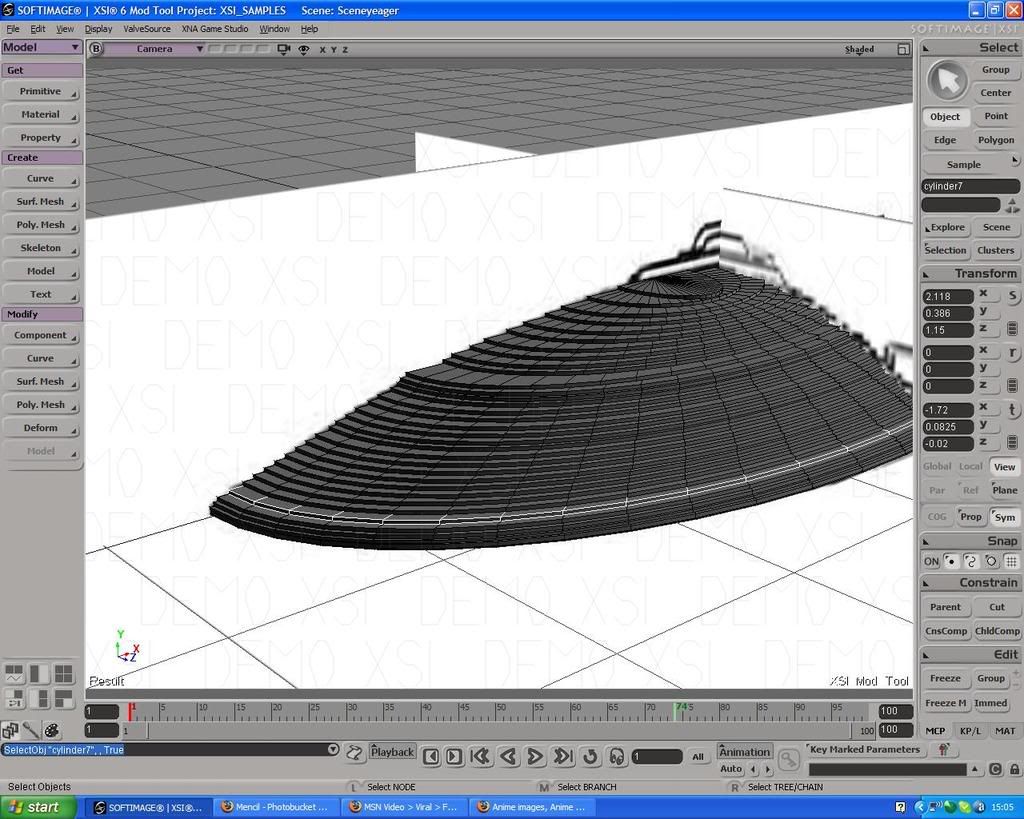
Here is how the model looks after we are done with the process:


You may end up with a very small flat section at the top of your model. What I find convenient, both for poly count and for later editing, is to select all the vertices of that section and use Modify->Poly.Mesh->Filter Points tool to merge them all into a single point. You can then move that vertice about to fit the rest of the shape.

We will now symmetrize our model. First, we have to remove the polygons in order to create the edges which will be welded automatically in the process. You always delete polygons on the side which is parallel to the plane of symmetry. For example, in the following picture:


You can see which polygons I removed, and the newly created edges outlined in light blue.

Now we can press "u" again and then "Ctrl-a" to select all the remaining polygons. Then we right-click and select "Symmetrize Polygons" option in the menu. Adjust the Plane Normal option (X, Y, or Z axis) depending on which direction you want the symmetry to go. In this case, its the X axis.

The result:


Naturally, we can complete the shape, by again removing necessary polygons, right clicking and symmetrizing, this time along the Z axis:


Or we can keep the front of the hull and this time use the back polygons as another cross-section, with a different set of curves to produce a different shape for the back portion of the hull.

This method may look complicated, but once you get used to it, it makes modelling curved shapes a lot simpler. Naturally, you cannot do *every* shape this way, but for base shapes, the ones you will later edit for the finer detail using the usual box-editing methods, its great, in my opinion.

Reply #10 Top
^^ Very close to how I'd approach it. In this specific ship's case, I'd build from a cylinder instead of a box, since it'll be easier to get even spacing of segments that way, but that's really just a personal preference-- the basic methodology is still the same.

Remember to be conservative with poly counts! Games have low-poly models out of necessity, due to performance needs. Poly budgets are much better these days, but it's still best to be frugal wherever possible. IIRC, the stock Sins meshes are somewhere around 4K polys for capital ships or so.
Reply #11 Top
Yes, of course. The above example has 1344 polygons, which may or may not be a bit too much, depending on the rest of the ship model.
Optimization is a whole other topic though! For quick reference, remember:

-flat surfaces do not need a lot of polygons
-when making curved surfaces, always strive for a balance between "looking smooth" and "making your computer explode"
-you can easily check your poly weight by pressing Spacebar, and then Shift-Enter

XSI has a great tool for optimizing meshes too heavy on the polygon side - Modify-Poly.Mesh-Polygon Reduction.
For example, this is how the example mesh looks after the tool has been used on it:


It will preserve your overall shape, while at the same time reducing the number of polygons needed to describe it (847 polygons in this case).
Reply #12 Top
Okay. I'm going to get some practice in then.
I shall consider this my training week. :)

Thank you for all your help once again. It would never have occured to me to model a saucer shape object in this way.

Some very good knews is that due to the nature of my job, I'm away from home for a month at a time with not much to do and this should give me something to do as well as helping focus my mind substantially. :D

Reply #13 Top
The reconstruction has begun!
I've been busy over the last few days so I'm only just starting now.
Here's a screen of the work so far. As you can see I've just about finished stage 1. I put a few more Base subdivisions more than entirely necessary in the interests of getting it right, though all they'll probably do is give me a higher poly count, but I figured I could rid myself of these later using poly reduction.


One thing I will say is, always ensure the symmentry button is dealt with before you try moving the points, otherwise you will spend an infuriating few minutes trying to work out why all the points are moving when you only want one to move (If you're at this stage yet you'll know what I'm talking about).

Let's hope that helps out any fellow newcomers to XSI.

Btw, what would be considered an acceptable poly count for Sins?
Reply #14 Top
Capital ships: anything up to 4000 polys
Cruisers: around 2000 polys
Frigates: The Lower The Better

As a general guide, use this: how often do you think the ship is going to appear in the game? Thus the poly count is highest for capitals and stations since you only get a handful of them on screen at any time, and lowest for frigates and strike craft since they appear in huge quantities.
Reply #15 Top
Okay, I'm much further on in the process now, and I've decided to divide it into parts and stages, for organisations sake. :)

Part 1:Saucer section
Stage 1:Cubes,subdivisions and prepping for curves
Stage 2:Duplication and repeatition <-----Me! :)
Stage 3:Symmetry+etc

Part 2:Main body/engineering section
Stage 1:General shape
Stage 2:Details
Stage 3:Nacelle pylons

Part 3:Warp Nacelles
Stage 1:Cylinder shape
Stage 2:Applying details

I think that's a simple but effective content index. If there's anything I've missed don't hesitate to say so.

And now, a picture!
*Roaring applause*